
AD8682/AD8684 are dual/quad low power, high-speed JFET operational amplifiers with features such as low supply current, high slew rate, wide bandwidth, low offset voltage, and low input bias current. They are suitable for applications such as portable telecommunications, low power industrial and instrumentation, loop filters, integrators, strain gauge amplifiers, portable medical instrumentation, and supply current monitoring.
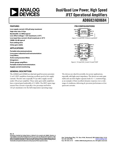
The AD8682 and AD8684 are dual‑ and quad‑channel JFET operational amplifiers designed for low‑power, high‑speed applications. They feature a typical slew rate of 9 V/µs, supply current under 250 µA per amplifier, and a typical gain‑bandwidth product of 3.5 MHz.
These devices are unity‑gain stable, support a wide common‑mode range (‑11 V to +15 V), and offer low offset voltage (1 mV max) and ultra‑low input bias current (20 pA max). The handbook includes pin configurations, absolute maximum ratings, thermal resistance data, and application notes such as high‑side signal conditioning and phase‑inversion protection.
| Slew Rate | 9 V/µs (typical) |
|---|---|
| Gain‑Bandwidth Product | 3.5 MHz (typical) |
| Input Offset Voltage | 1 mV max (typical) |
| Input Bias Current | 20 pA max (typical) |
| CMRR | 90 dB (typical) |
| Power Supply Range | ±4.5 V to ±18 V |
The typical slew rate is 9 V/µs.
The maximum input bias current is 20 pA at 25 °C.