
This document is the user manual of TC9400/9401/9402, which are low-cost Voltage-to-Fre- quency (V/F) converters with low power dissipation and high accuracy. It can be used in Microprocessor Data Acquisition, 13-bit Analog-to-Digital Converters (ADC), Analog Data Transmission and Recording, Phase Locked Loops, Frequency Meters/Tachometer, Motor Control and FM Demodulation applications.
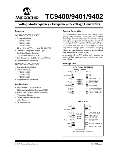
The TC9400, TC9401 and TC9402 are low‑cost voltage‑to‑frequency (V/F) and frequency‑to‑voltage (F/V) converters built with low‑power CMOS technology. They accept an analog input and generate a pulse‑train output whose frequency is linearly proportional to the input voltage, or vice‑versa for frequency‑to‑voltage operation.
The document provides functional block diagrams, pin descriptions, electrical characteristics, recommended external components and application guidance such as data acquisition, motor control and PLL use.
| Linearity (10 kHz) | TC9400 0.05 %, TC9401 0.01 %, TC9402 0.25 % |
|---|---|
| Gain Temperature Stability | +25 ppm/°C (typical) |
| Low Power Dissipation | 27 mW (typical) |
| Supply Voltage Range | +8 V to +15 V or +4 V to +7.5 V |
The typical power dissipation is 27 mW.
The devices operate from +8 V to +15 V or from +4 V to +7.5 V.
Gain temperature stability is +25 ppm/°C typical.
At 10 kHz the TC9400 has 0.05 % linearity, TC9401 0.01 %, and TC9402 0.25 %.