
This document introduces the free trial version of CAD software, which includes functions such as schematic editing, layout editing, and autorouting. The software has 20 years of experience and success, and can design entire circuit boards and generate manufacturing data.
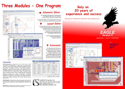
This manual covers the three core modules of EAGLE 5 – the Schematic Editor, Layout Editor and Auto Router – and shows how they work together to create PCB designs. It also describes the Design Rule Check, Library Editor and integrated CAM processor for generating manufacturing data.
Additional sections explain the technical limits of the software, such as layer count, routing grid size, drawing area and supported via types, as well as the differences between the Professional, Standard and Light editions.
| Smallest routing grid | 0.02 mm |
|---|---|
| Maximum drawing area | 1.6 m × 1.6 m |
| Resolution | 1/10 000 mm |
| Supported signal layers | up to 16 |
| Maximum drawing layers | 255 |
| Via types supported | blind, buried, micro vias |
The smallest routing grid is 0.02 mm.
EAGLE 5 can handle up to 16 signal layers.
Yes, EAGLE 5 includes a Design Rule Check (DRC) to verify design constraints.
The maximum drawing area is 1.6 m × 1.6 m (64 in × 64 in).