
This document describes the mounting and installation of the GML20 LonWorks® interface module, which enables communication between a LonWorks® network and GM20 series transmitters over a twisted pair
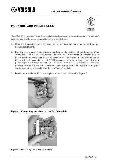
This guide describes the mounting and installation steps for the GML20 LonWorks® interface module, which enables communication between a LonWorks® network and GM20 series transmitters. It covers opening the transmitter cover, removing the jumper, routing the output wires, and connecting them to the module's NET terminal.
The document also explains the configuration procedure using the service button, the meaning of the status LED, technical data of the module, and the one‑year guarantee provided by Vaisala under normal operating conditions. This manual is written in Chinese.
| Network Type | LonWorks® interoperable twisted pair free topology TP/FT at 78 kbs |
|---|---|
| Power Supply | Nominal 24 V supplied between terminals + and – on the transmitter motherboard |
| Additional Wiring | Two extra wires required for powering the transmitter |
| External Interface File | Available on request (part no. 19412GM) |
Remove the jumper from the pin connector, pull the two output wires through the housing, and attach them to the NET terminal of the GML20 module, selecting polarity as needed.
A dark LED means the transmitter configuration and operation are correct; a lit LED signals a fault; a blinking LED shows the transmitter has not been configured.