
The NE5565 is a high power factor, low harmonic distortion, good anti-surge protection electronic ballast controller chip.
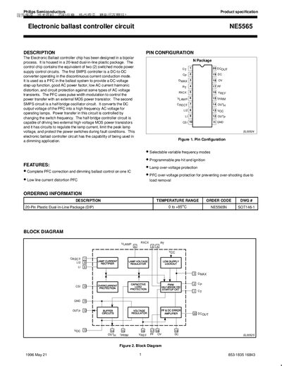
The NE5565 is a dual‑function electronic ballast controller IC designed for fluorescent lamp applications. It integrates a power‑factor correction (PFC) front‑end and a half‑bridge oscillator for lamp driving, offering selectable frequency modes, dimming support, and comprehensive protection features.
The datasheet provides detailed pin configurations, absolute maximum ratings, electrical characteristics, and typical application circuits, enabling designers to implement the IC in 2‑lamp dimming ballast designs and other lighting solutions.
| Package | 20‑lead DIP (plastic dual‑in‑line) |
|---|---|
| Reference Output Voltage (Vref) | 7.42 V |
| Nominal VCC Voltage | 12.7 V |
| Minimum Supply Voltage | 9.3 V |
The NE5565 provides a regulated reference voltage of 7.42 V on the Vref pin.
The IC comes in a 20‑lead dual‑in‑line (DIP20) plastic package.
The OV pin monitors the PFC output voltage; if it exceeds the reference (≈7.42 V) the output driver is turned off for over‑voltage protection.