
The Philips Semiconductors NE5565 Electronic Ballast controller circuit is a chip that can be used for electronic ballasts. It includes two switched mode power supply control circuits that can provide DC voltage step-up functions, good AC power factor, low AC current harmonic distortion, and protection against some types of AC voltage transients.
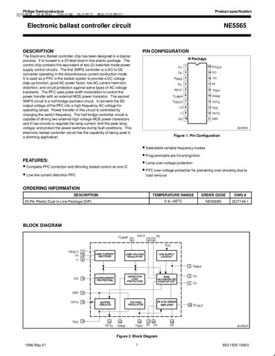
The NE5565 is a 20‑lead dual‑in‑line IC that integrates two switched‑mode power supply (SMPS) control circuits for fluorescent lamp ballasts. It provides power‑factor correction, dimming control, lamp over‑voltage protection, and various fault protections in a single chip.
The document details pin functions, absolute maximum ratings, electrical characteristics, and typical application schematics, enabling designers to implement the controller in AC line‑powered lighting systems.
| Package | 20‑lead dual‑in‑line plastic (DIP20) |
|---|---|
| Regulated Vref Output | 7.42 V |
| Nominal VCC Supply Voltage | 12.7 V |
| Pin Count | 20 pins |
It prevents the PFC DC output voltage from exceeding a preset value by turning off the OUTp output when the voltage at the OV pin is greater than the Vref voltage.
The Vref pin provides a regulated 7.42 V reference.