
The ISL6424 is a highly integrated voltage regulator and interface IC, specifically designed for supplying power and control signals from advanced satellite set-top box (STB) modules to the low noise blocks (LNBs) of two antenna ports. The device is comprised of two independent current-mode boost PWMs and two low-noise linear regulators along with the circuitry required for 22kHz tone generation, modulation and I2C device interface. The device makes the total LNB supply design simple, efficient and compact with low external component count. Two independent current-mode boost converters provide the linear regulators with input voltages that are set to the final output voltages, plus typically 1.2V to insure minimum power dissipation across each linear regulator. This maintains constant voltage drops across each linear pass element while permitting adequate voltage range for tone injection. The final regulated output voltages are available at two output terminals to support simultaneous operation of two antenna ports for dual tuners. The outputs for each PWM are set to 13V or 18V by independent voltage select commands (VSEL1, VSEL2) through the I2C bus. Additionally, to compensate for the voltage drop in the coaxial cable, the selected voltage may be increased by 1V with the line length compensation (LLC) feature. All the functions on this IC
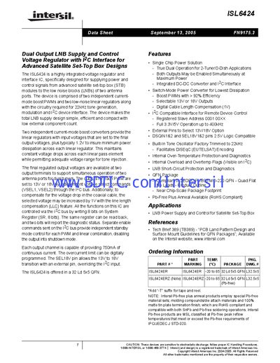
The ISL6424 is a highly integrated dual‑output voltage regulator and interface IC designed for satellite set‑top box LNB power and control. It combines two current‑mode boost converters, two low‑noise linear regulators, a 22 kHz tone generator, DiSEqC encoding, and an I²C interface, allowing simultaneous operation of two LNBs with selectable 13 V or 18 V outputs.
The datasheet provides pin‑out diagrams, block diagrams, and electrical specifications such as a supply voltage range of 8‑14 V, 750 mA continuous output per channel, efficiency >92 %, and an operating temperature range of –20 °C to 85 °C. It also describes I²C register maps, dynamic current limiting, thermal shutdown, and package dimensions (32‑lead 5 × 5 mm QFN).
| Continuous output current per channel | 750 mA |
|---|---|
| Selectable output voltage | 13 V or 18 V |
| Boost converter efficiency | >92 % |
| Operating supply voltage range | 8 V to 14 V |
| Standby supply current | 1.5 mA – 3.0 mA |
| Operating temperature range | -20 °C to 85 °C |
| Tone frequency | 22 kHz |
| I²C clock frequency max | 400 kHz |
Each output channel can provide 750 mA of continuous current.
The output voltage can be set to 13 V or 18 V via the VSEL bits or by pulling the SEL18V pins high for 18 V; a 1 V line‑length compensation can also be added.
The device operates from –20 °C to 85 °C.
The I²C bus can run up to 400 kHz.