
ISL6401 Synchronizing Current Mode PWM for Subscriber Line Interface Circuits (SLICs)
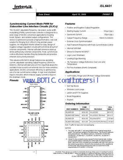
The ISL6401 is an adjustable‑frequency, low‑power PWM current‑mode controller designed for DC‑DC conversion applications such as boost, flyback, and isolated output configurations. It integrates an inverter for negative‑voltage regulation and includes internal soft‑start and over‑current protection.
Key features include positive and negative output regulation, external clock synchronization, a wide output‑frequency range of 50 kHz to 600 kHz, and a logic‑level shutdown input. Typical applications are VoIP/VoDSL ringers, set‑top boxes, wireless local loops, and power supplies for routers and other telecom equipment.
| Supply Voltage Range | 5.0 V – 5.5 V |
|---|---|
| Output Frequency Range | 50 kHz – 600 kHz |
| Starting Supply Current | 100 µA (typ) |
| Maximum Duty Cycle | 50 % |
The SYNC pin is the input for external frequency synchronization, allowing the oscillator to be locked to an external clock.
The device has an internal digital soft‑start that clamps the COMP voltage and reference input, requiring no external components.
The recommended supply voltage range is 5.0 V to 5.5 V.