
HIN202, HIN206, HIN207, HIN208, HIN211, HIN213 +5V Powered RS-232 Transmitters/Receivers with 0.1Microfarad External Capacitors
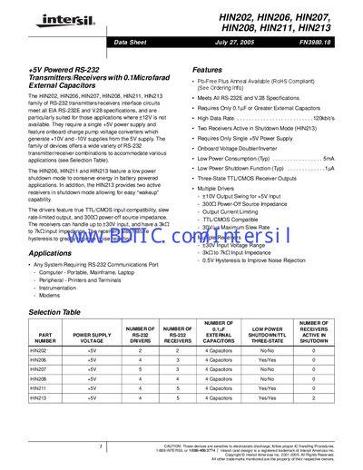
The HIN202‑HIN213 series are +5 V powered RS‑232 transmitters/receivers that meet all EIA RS‑232E and V.28 specifications and generate internal +10 V and –10 V supplies from a single +5 V source. They offer low power consumption, optional shutdown mode, and a variety of driver/receiver configurations.
The document provides pin descriptions, detailed pinout diagrams for each package type, absolute maximum ratings, electrical specifications, timing characteristics, and ordering information including package options and temperature ranges. Mechanical dimensions for SOIC and SSOP packages are also included.
| Supply Voltage | +5 V |
|---|---|
| Shutdown Supply Current (HIN213) | 50 pA |
| External Capacitor Requirement | ≥ 0.1 µF |
| RS‑232 Input Voltage Range | -30 V to +30 V |
The devices require external capacitors of 0.1 µF or greater.
Two receivers stay active in shutdown mode for the HIN213.
V+ may be up to 12 V.