
The AT24C32C/64C is a serial electrically erasable and programmable read-only memory (EEPROM) with low power and low voltage operation. It provides 32,768/65,536 bits of storage space and is accessed via a 2-wire serial interface. The device is suitable for many industrial and commercial applications.
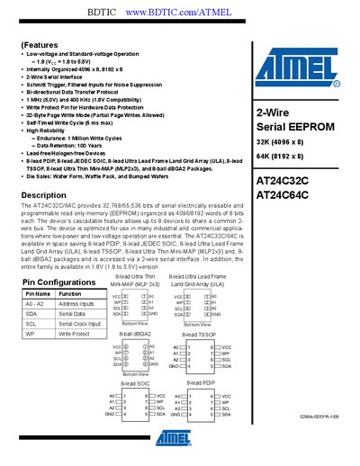
The AT24C32C/AT24C64C series provides 32‑kbit and 64‑kbit serial EEPROM memory organized as 4096 × 8 and 8192 × 8 bits respectively. The devices operate over a 1.8 V to 5.5 V supply range and support low‑power, low‑voltage applications with up to eight devices cascaded on a common 2‑wire I²C bus.
The datasheet includes electrical characteristics, pin descriptions, timing diagrams, and operating procedures such as write protection, standby mode, and software reset. Package options include PDIP, SOIC, TSSOP, ULA, MLP, and BGA variants.
| Supply Voltage (VEE) | 1.8 V to 5.5 V |
|---|---|
| Operating Temperature | -55 °C to +125 °C |
| Endurance | 1 Million write cycles |
| Data Retention | 100 years |
| Page Write Mode | 32‑byte page write (partial page writes allowed) |
| Maximum Clock Frequency | 400 kHz (1.8 V) to 1 MHz (5 V) |
Up to eight devices can be cascaded on the same bus.
When WP is high, all write operations are inhibited; when WP is low, normal write operations are allowed.
The EEPROM enters low‑power standby mode after power‑up and after a stop condition is received.