
The MAX7391 is a product that replaces ceramic resonators, crystals, and supervisory functions for microcontrollers in 3.3V and 5V applications. It provides a clock source, reset, and power-fail functions. The programmable power-fail function provides early warning of power failure and can be configured to detect either an external voltage or the VCC supply to the device. The clock output can be switched between normal and half-speed operation. This functionality allows the microcontroller to operate at reduced power and may be used to extend the time available to perform housekeeping tasks, such as writing data to flash during a power failure. Connecting the power-fail output to the SPEED input reduces clock speed automatically during power-fail events. The MAX7391 clock output is factory programmed to a frequency in the 1MHz to 16MHz range. Four standard frequencies are available. Other frequencies are available upon request. The maximum operating supply current is 5.5mA (typ) with a clock frequency of 12MHz. Unlike typical crystal and ceramic resonator oscillator circuits, the MAX7391 is resistant to EMI and vibration, and operates reliably at high temperatures. The high-output drive current and absence of high-impedance nodes make the oscillator invulnerable to dirty or humid operating conditions. The MAX7391 is available in an 8-pin µMAX® package. The MAX7391 standard operating temperature range is from -40°C to +125°C.
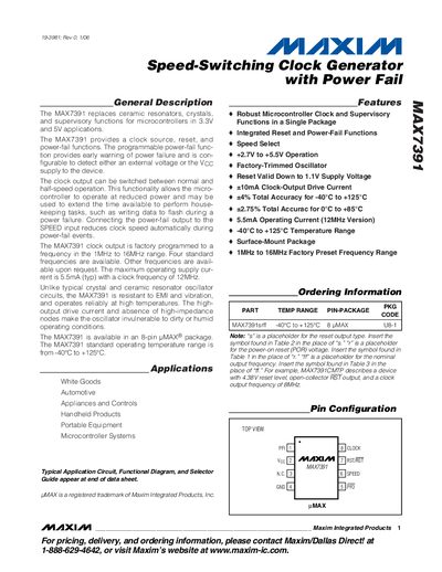
The MAX7391 replaces ceramic resonators and crystals, providing a programmable clock source, reset, and power‑fail monitoring for 3.3 V and 5 V microcontroller applications. The clock output can operate at the factory‑trimmed frequency (1 MHz‑16 MHz) or be halved by pulling the SPEED input low, allowing reduced power consumption during power‑fail events.
The device includes integrated reset circuitry with two factory‑trimmed levels, a power‑fail comparator that can monitor either an external voltage or VCC, and a robust CMOS push‑pull clock output capable of 10 mA drive current. It is supplied in an 8‑pin UMAX surface‑mount package and operates from –40 °C to +125 °C.
| Operating Supply Voltage | 2.7 V to 5.5 V |
|---|---|
| Clock Output Frequency Range | 1 MHz to 16 MHz (factory‑preset) |
| Clock Output Drive Current | ±10 mA |
| Operating Temperature Range | -40 °C to +125 °C |
| Maximum Operating Supply Current (12 MHz version) | 5.5 mA (typ) |
| Reset Valid Down to | 1.1 V |
| Package | 8‑pin UMAX (surface‑mount) |
| Reset Timeout Period | ≈135 s |
The device operates from 2.7 V up to 5.5 V supply voltage.
When SPEED is high, the clock runs at the factory‑trimmed frequency; pulling SPEED low halves the output frequency.
The reset output remains asserted for approximately 135 seconds before being released.
The internal VCC rising threshold (ViTH) is set at 4.38 V.