
CNC 8070 (REF. 0601) hardware configuration. This document describes the hardware components of CNC 8070, including central processing unit (CPU), screen, keyboard, operation panel, etc.
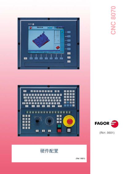
The document describes the hardware architecture of the Fagor CNC 8070, including PC104 modules, various LCD panels (LCD‑10, LCD‑10K, LCD‑12, LCD‑15) and the OP‑Panel‑HE interface. It also covers communication options such as CAN and Sercos, and details the overall wiring and grounding scheme.
Safety and compliance information is included, referencing European standards (EN 60204‑1, EN 50081‑2, EN 55011, EN 61000‑3‑2, EN 61000‑3‑3) and providing guidelines for electromagnetic compatibility and machine‑tool safety devices. This manual is written in Japanese.
| Safety standards | EN 60204-1, EN 50081-2, EN 55011, EN 61000-3-2, EN 61000-3-3 |
|---|
It complies with EN 60204-1, EN 50081-2, EN 55011, EN 61000-3-2 and EN 61000-3-3.
The controller supports CAN and Sercos communication interfaces.
Supported LCD panels include LCD-10, LCD-10K, LCD-12 and LCD-15.
All grounding points must be tied together before connecting to ground.