
This document discusses the impact of frequency feedback/installation techniques on the accuracy of sensors. A larger contact area between the sensor and the equipment results in more accurate high-frequency feedback. Sensors connected with screws or epoxy adhesive maximize the contact area, making them suitable for high-frequency feedback measurements. The accuracy of low-frequency feedback is independent of the installation method. The document provides examples of different installation techniques and their corresponding high-frequency feedback capabilities.
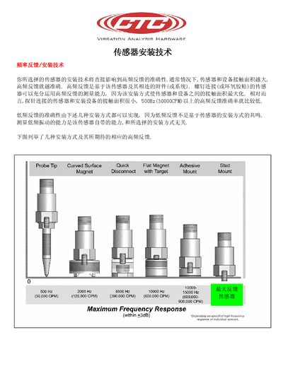
This manual explains the installation techniques for CTC vibration analysis sensors. It emphasizes that larger contact areas between the sensor and the mounting surface improve high‑frequency response, while smaller contact areas reduce it.
Various probe tip options are listed, including curved surface, quick flat, magnet, adhesive, and stud mounts. Frequency response charts show performance from 500 Hz up to 15 kHz, illustrating how different mounting methods affect sensor accuracy. This manual is written in Japanese.
| Frequency response range | 500 Hz – 15 kHz |
|---|
A probe tip with a large contact area, such as a curved surface, provides the highest high‑frequency response.
Frequencies above 500 Hz, up to 15 kHz, are regarded as high‑frequency.