
DVPDT02-H2 is an OPEN-TYPE device used for controlling operating machines and equipment. Only qualified professional staff familiar with its structure and operation can install, operate, wire, and maintain it. Make sure the ground terminal is correctly grounded to prevent electromagnetic interference.
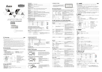
The Delta DVPDT02-H2 is an open‑type DeviceNet communication module designed for connection with DVP‑EH2 series PLCs. It supports Group 2 servers, explicit master/slave connections, configurable I/O data length, polling and EDS files.
The manual provides safety warnings, installation guidelines, wiring instructions, configuration of node address and DIP switches, LED status meanings, control register details, and error‑code troubleshooting. It is intended for qualified personnel only. This manual is written in Chinese.
| Operating voltage | 11 ~ 25 V DC |
|---|---|
| DeviceNet current | 28 mA typical, 125 mA impulse (24 V DC) |
| Transmission speed | 125 kbps, 250 kbps, 500 kbps |
| Maximum I/O data length | 200 bytes |
| Electrical isolation | 500 V DC |
| Operating temperature | 0 °C ~ 55 °C |
| Storage temperature | -25 °C ~ 70 °C |
| Certifications | CE, UL |
The module requires 11 V to 25 V DC, which is supplied by the power cable in the DeviceNet network.
Use the two rotary switches to set the address in decimal, ranging from 00 to 63; the setting takes effect after the module is powered on again.
POWER shows whether the module has power; NS indicates network status; MS indicates module status such as online, data exchange, or fault conditions.