
The example program describes the single pulse output function of the 16-bit timer/event counter 00. The single pulse output function is used to output a single pulse after a given delay time after detecting an external signal on the TI000 pin. In addition, the effective pulse width changes depending on the number of switch inputs.
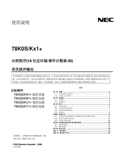
This manual describes an example program that uses the 16‑bit timer/event counter 00 of the NEC 78K0S/Kx1+ microcontroller to generate a single pulse after detecting a rising edge on the TI000 pin. It explains initial configuration, timing parameters, and interrupt handling for pulse width control.
The document includes circuit diagrams, a list of supplied source files, and detailed settings for internal peripherals such as the low‑voltage detector, watchdog timer, and clock source. It also provides revision history and contact information for NEC technical support in China. This manual is written in Chinese.
| CPU clock frequency | 8 MHz |
|---|---|
| Internal high‑speed oscillator | Used as system clock source |
| Watchdog timer | Stopped |
| Low‑voltage detection (LVI) threshold | 4.3 V ± 0.2 V |
| Vpp operating range | 4.5 V – 5.5 V |
| Timer clock source | fX/22 (2 MHz) |
| Delay time before pulse | 1 ms |
| Single‑pulse width | 10 ms |
The CPU clock frequency is set to 8 MHz.
When a rising edge is detected on the TI000 pin, the program waits the configured delay (1 ms) and then outputs a single pulse of the configured width (10 ms).
Vpp must be between 4.5 V and 5.5 V.
The internal high‑speed oscillator is selected as the system clock source.