
This is a user document about MICROMASTER 430 universal frequency converter, which introduces the installation, debugging, control mode, system parameters, troubleshooting, technical specifications, and optional accessories of the product.
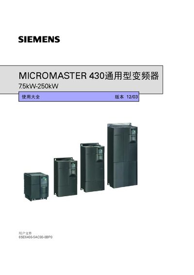
This manual covers the complete lifecycle of the MICROMASTER 430 variable‑frequency drive, from safe installation and wiring to commissioning, normal operation, and routine maintenance. It is intended for qualified personnel who will install, program, and service the drive in industrial applications.
The document is organized into sections on overview, mechanical and electrical installation, commissioning with SDP and BOP‑2 panels, detailed parameter tables, fault diagnostics, optional accessories, EMC compliance, and communication interfaces. Technical data such as power range, input voltage, I/O counts, and overload capabilities are listed in the specifications chapter. This manual is written in Chinese.
| Power range | 7.5 kW – 250 kW (10 hp – 120 hp) |
|---|---|
| Input voltage | 380 V – 480 V AC ±10% |
| Input frequency | 47 Hz – 63 Hz |
| Output frequency | 0 Hz – 650 Hz |
| Power factor | 0.98 |
| Overload capability (110% load) | 60 s |
| Pulse modulation frequency | 2 kHz – 8 kHz |
| Digital inputs | 6 programmable |
| Analog inputs | 2 (0‑10 V, 0‑20 mA, –10‑+10 V) |
| Relay outputs | 3 (30 V DC/5 A, 250 V AC/2 A) |
| Serial communication interface | RS‑485 (optional RS‑232) |
The drive accepts three‑phase AC voltage from 380 V to 480 V with a tolerance of ±10 %.
It provides six programmable digital inputs.
The maximum selectable output frequency is 650 Hz.
The drive includes an RS‑485 interface and an optional RS‑232 interface.