
Key facts
- Brand
- EPRC10-ST
- Model
- EPRC10-ST
- Category
- Power Management
- Documents
- 2
- Languages
- ZH
- Last added
- 2012-04-09
Start here
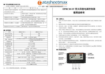
EPRC10-ST Solar Power Supply Controller User Manual
This manual describes the features and specifications of the EPRC10-ST solar power supply controller, including PWM charging, temperature compensation, and various protection functions such as over‑charge, over‑discharge, short‑circuit, overload and reverse‑polarity protection. It also explains the LED indicators that show charging status, battery condition and load status.
Installation steps cover secure mounting, wiring of the battery, solar panel and load, and the use of the one‑key touch switch for all settings. Operating instructions detail how to interpret the indicator lights, select working modes, and adjust timing and output modes. A troubleshooting section lists common fault symptoms and their corrective actions. This manual is written in Chinese.
EPRC10-ST specifications
| Model | EPRC10-ST |
|---|---|
| Rated charging current | 5 A (EPRC10-ST 5) / 10 A (EPRC10-ST 10) |
| Rated load current | 5 A (EPRC10-ST 5) / 10 A (EPRC10-ST 10) |
| System voltage | 12 V; 24 V/12 V AUTO |
| Overload protection time | 5 s at 1.5× rated current |
| Short‑circuit protection | At rated current |
| No‑load loss | 6 mA |
| Charging circuit voltage drop | ≤0.26 V |
| Discharging circuit voltage drop | ≤0.15 V |
| Operating temperature range | -35 °C to +55 °C |
| Control method | PWM (pulse‑width modulation) |
All EPRC10-ST documents by type
Day-to-day operation, settings and troubleshooting. Start here if the product is already set up.
Questions answered in these manuals
How do I reset the controller after an overload or short‑circuit?
Press the switch button once; after about 30 seconds the controller restores normal output.
What does the green charging indicator light mean?
When the solar panel receives sunlight, a steady green charging indicator shows that the charging circuit is operating normally.
What does the charge indicator light mean?
When the charge indicator (LED 1) stays steady green, the charging circuit is operating normally; if it flashes rapidly, the controller is in the charging phase.
How should the controller be connected to the solar panel?
Connect the solar panel’s positive lead to the controller’s “+” terminal and the negative lead to the “–” terminal, ensuring correct polarity; reverse connection will trigger the reverse‑polarity indicator.