
This product is a controller designed for solar DC power systems and solar DC street lighting systems. It has short circuit, overload, unique reverse connection protection, full, over discharge automatic recovery and other functions.
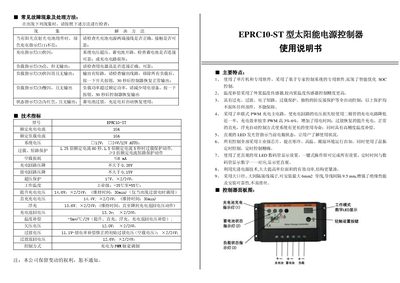
This manual provides detailed instructions for installing, wiring, and operating the EPRC10-ST solar power supply controller. It includes safety precautions, connection diagrams, and step‑by‑step procedures for normal use and for configuring the various operating modes such as PWM charging, light‑controlled delay, and timer functions.
The document also describes fault symptoms and troubleshooting methods, explains the meaning of the indicator LEDs, and lists the technical specifications of the controller, including rated charge and load currents, input voltage range, operating temperature, and mechanical dimensions. This manual is written in Chinese.
| Rated charge current | 10 A |
|---|---|
| Rated load current | 10 A |
| Input voltage | 12 V, 24 V/12 V AUTO |
| Operating temperature | -35 °C to 155 °C |
| Dimensions (width × height) | 133 mm × 70 mm |
| Mounting hole size | 126 mm × 50 mm |
When the charge indicator (LED 1) stays steady green, the charging circuit is operating normally; if it flashes rapidly, the controller is in the charging phase.
Connect the solar panel’s positive lead to the controller’s “+” terminal and the negative lead to the “–” terminal, ensuring correct polarity; reverse connection will trigger the reverse‑polarity indicator.
Yes, the controller is designed to function from –35 °C up to 155 °C, making it suitable for both cold and hot environments.