
Technical manual for the Siemens JB521C23 KNX solar protection actuator with two relay outputs for controlling blinds, shutters, and awnings.
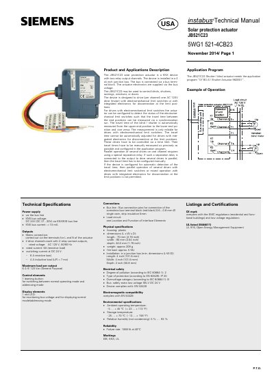
The Siemens JB521C23 is a KNX solar protection actuator designed for installation in a 4x4 inch junction box. It provides two relay output channels to drive AC 120V motors for blinds, shutters, awnings, windows, or doors. The actuator electronics are powered via the KNX bus voltage (DC 24V). It supports drives with electromechanical limit switches or integrated electronic disconnection, and can automatically measure travel time for the former.
The device includes a learning button for addressing mode, a red LED for status indication, and screwless bus terminal blocks for connection. It complies with EN 50428 and UL 916, carries CE and UL marks, and operates in temperatures from -5°C to +45°C. Mounting options include inside or outside a junction box using a 1/2 inch thread nut. Wiring uses AWG #14 wires for motor and mains connections.
| KNX bus voltage | DC 24V (DC 21...30V) |
|---|---|
| KNX bus current | < 10 mA |
| Number of output channels | 2 |
| Rated voltage per channel | AC 120 V, 50/60 Hz |
| Rated current (resistive) | 6 A |
| Maximum load per output | 6 A @ 120 Vac |
| Dimensions (L x W x D) | 70 mm x 90 mm x 44.6 mm |
| Weight | approx. 209 g |
| Operating temperature | -5 ... +45 °C |
| Protection class | IP 20 |
The actuator is powered via the KNX bus at DC 24V (range DC 21...30V).
The JB521C23 has two relay output channels.
The device needs the application program “07 B0 A1 Shutter Actuator 982B01”.
Each output can handle a maximum of 6 A at 120 Vac (General Purpose).