
Patlite LME Series Indicators Wiring and Mechanical Diagrams

Technical diagrams and notes for Patlite LME Series indicators, including wiring configurations, mechanical layouts, and installation warnings.
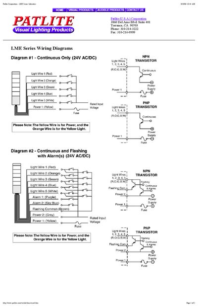

Patlite LME Series Indicators Wiring and Mechanical Diagrams - cover page
Brand
Patlite
Category
Other Electronics
Document type
Product Leaflet
Language
English
Pages
3
File format
PDF
File size
728 KB
Published
12 October, 2026
Updated
12 October, 2026
MD5 checksum
9C8FD641F6EDD270FB429FEF836D5255

About this manual

This document provides technical diagrams for the Patlite LME Series indicators, specifically covering wiring diagrams and mechanical diagrams. It includes details on wire color codes and component connections.

What's inside

  • Wiring Diagrams
  • Mechanical Diagrams
  • Notes
  • Installation
  • Wire Color Codes
  • Fuse Rating
  • Customer Supplied Components

Specifications

Fuse Rating1A

Frequently asked questions

Are transistors, switches, and fuses included with the indicator?

No, transistors, switches, and fuses shown are to be supplied by the customer.

Which wire is omitted from the Continuous Only version for 120V AC models?

The Continuous Only version does not include the Flashing Common (Brown) wire.

What is the required fuse rating for this indicator?

The fuse rating must be 1A.

Download PDF (728 KB)

More Patlite Manuals


View all Patlite manuals →