
Operating instructions for the OAKTON 1000 series 1/4 DIN conductivity and resistivity controller, covering installation, calibration, setup, and control.
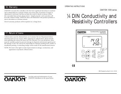
This manual covers the OAKTON 1000 series 1/4 DIN conductivity or resistivity controller. It describes installation, keypad and display, startup, calibration, advanced setup, alarm relay, measurements, manual control, specifications, accessories, and appendices.
The controller includes two set-point SPDT relays, an alarm relay, 0-20/4-20 mA output, and adjustable temperature compensation.
| Housing dimensions | 3.78 x 3.78 in (96 x 96 mm) |
|---|---|
| Front panel protection | IP 54 |
| Maximum panel thickness | 45 mm |
| Power supply | 110 or 220 VAC (selectable) |
| Temperature sensor input | Pt100 or Pt1000 (selectable) |
| Cell constants | 0.01, 0.1, 1.0, or 10.0 |
| Analog output | 0-20 or 4-20 mA |
| Relay outputs | Two set point, two SPDT relays |
| Relay time delay | 0 to 2000 seconds |
| Temperature coefficient | 0.00 to 10.00% per °C |
The controller includes a 17-way and a 5-way right angled terminal block, two side threaded rods with catch, one receptacle cable lug, and one rubber gasket.
Power is selectable for 110 or 220 VAC via an internal jumper, and the factory setting is indicated on the label on top of the controller.
It forces the relays to their resting position by applying a contact closure across terminals 13 and 14.
The alarm relay functions as an Active Low device and switches OFF under alarm condition, so the alarm display device should be connected to the NC contacts.