
User guide for Maxim's MAX22501E evaluation kit, a PCB for testing RS-485/RS-422 transceiver performance with 3V-5V power and selectable termination.
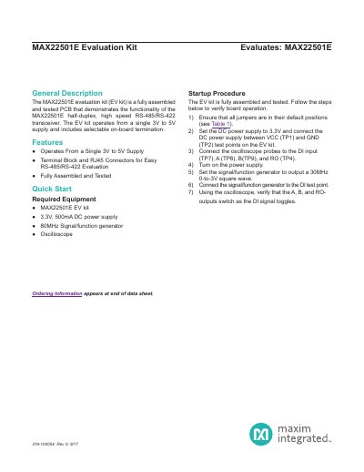
This document provides instructions for using the MAX22501E Evaluation Kit, a fully assembled PCB designed to test the MAX22501E half-duplex RS-485/RS-422 transceiver. It operates on a single 3V to 5V supply and includes selectable on-board termination for easy evaluation. The guide covers startup procedures, hardware details, jumper configurations, and component specifications.
The kit includes terminal blocks and RJ45 connectors for RS-485/RS-422 testing, and features a schematic and PCB layout for reference. Users are instructed to set jumpers, connect power, and use an oscilloscope and signal generator to verify functionality.
| Operating Voltage | 3V to 5V |
|---|---|
| Transceiver Type | Half-duplex, high-speed RS-485/RS-422 |
| Termination | Selectable on-board termination |
| Test Points | TP1 (VCC), TP2 (GND), TP4 (RO), TP7 (DI), TP8 (A), TP9 (B) |
It operates from a single 3V to 5V supply.
Set J2 to low (2-3) to enable the receiver, and J4 to high (1-2) to enable the driver.
The kit includes capacitors, resistors, jumpers, connectors, and the MAX22501E transceiver.