
This application note explains how to connect a two‑wire Bently Nevada Velomitor to a Pepperl+Fuchs KFD2‑VR4‑EX1.26 voltage repeater for use with a 3500/42M…
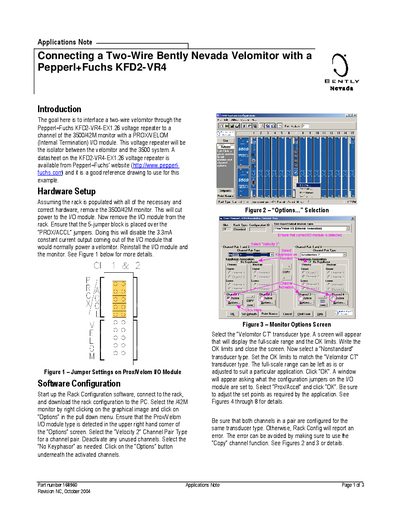
The note describes the hardware setup required to interface the Velomitor with the KFD2‑VR4‑EX1.26 isolator, including jumper settings, external power supply connection, and wiring polarity. It also warns that the 3500/42M monitor cannot supply enough current for the isolator, so a +24 VDC external supply must be used.
Software configuration steps are provided for the Rack Configuration software, covering channel pair selection, transducer type settings, and OK‑limit adjustments. The document lists conditions that trigger a NOT OK state on the monitor and points to additional resources on both manufacturers' websites.
| External power supply voltage | +24 VDC |
|---|---|
| Constant current flow on KFD2 input | 3.6 mA |
| Jumper setting to disable 3.3 mA output | 5‑jumper block over “PROX/ACCL” |
| Ground polarity of Velomitor | Positive common system |
Use a +24 VDC external power supply connected to terminals 11 (+) and 12 (‑) of the isolator, and do not activate the supply until the jumper is placed.
Place the 5‑jumper block over the “PROX/ACCL” jumpers on the Prox/Velom I/O module.
A NOT OK state occurs if the Velomitor probe is not connected, if the Velomitor signal is shorted, if the isolator signal is not connected, or if the isolator signal is shorted.