
Analog Devices DC2480A demo manual covers the LTC4283 -48V, 400W hot swap board, setup, power connections, power good control, and I2C interfaces.
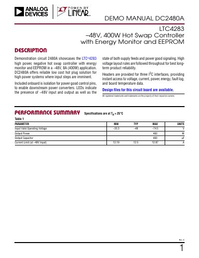
This Analog Devices DEMO MANUAL describes DC2480A, a demonstration circuit for the LTC4283 high power, negative hot swap controller with energy monitor and EEPROM in a −48V, 8A (400W) application. It states that the board provides a low cost hot plug solution for high power systems where input steps are imminent.
The manual covers quick start procedures, board layout, power connections, power good control, J1/J2 digital interface setup, supply monitor inputs, board temperature measurement, altered register values, and basic operation. It also describes LEDs, isolation for power good control pins, headers for three I2C interfaces, and use with DC590, DC1613, and DC2026 interface boards.
| Input Valid Operating Voltage | –35.3 V min; –48 V typ; –74.5 V max |
|---|---|
| Output Power | 400 W |
| Output Capacitor | 400 µF |
| Current Limit at –48V Input | 12.19 A min; 12.5 A typ; 12.87 A max |
| I2C Interfaces | Headers for three I2C interfaces |
| Power Good Control | Two outputs and one input |
| Board Plane DC Standoff | Up to 100V with 60mil gaps |
| Power Connection Cable | 4 AWG (19mm2) welding cable |
| Mounting Torque | 5ft/lbs (6.8Nm) maximum |
It demonstrates the LTC4283 high power, negative hot swap controller with energy monitor and EEPROM in a −48V, 8A (400W) application.
The performance summary lists 400 W output power and a 400 µF output capacitor.
PGI# INPUT must be asserted within 512ms after PG2# goes low; if not, the LTC4283 will shut down.
No. A ribbon cable connects J1 or J2 to the interface board; do not use J1 and J2 simultaneously.