
This application note describes the features, connectors, and demonstration circuits of the Analog Devices ADuC7020 MicroConverter evaluation board.
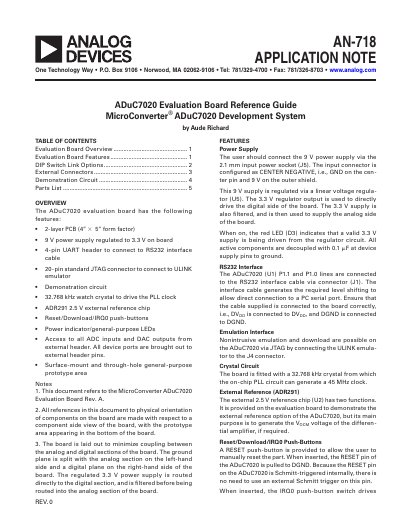
The document provides an overview of the ADuC7020 evaluation board, detailing its 2-layer PCB design, power supply regulation from 9V to 3.3V, and various interface headers including UART, JTAG, and I2C. It specifies that the board includes a demonstration circuit for ADC/DAC testing and a general-purpose prototype area.
| Power Supply Input | 9 V regulated to 3.3 V |
|---|---|
| Watch Crystal Frequency | 32.768 kHz |
| External Reference Voltage | 2.5 V |
Hold down the serial download push-button while inserting and releasing the reset button.
It serves as a 2.5 V external reference for the ADuC7020 and generates the V OCM voltage for the differential amplifier.
The P1.1 and P1.0 lines of the ADuC7020 are connected via connector J1.