
The Analog Devices ADP1612/ADP1613 datasheet provides specifications, features, and application information for these step‑up PWM DC‑DC converters.
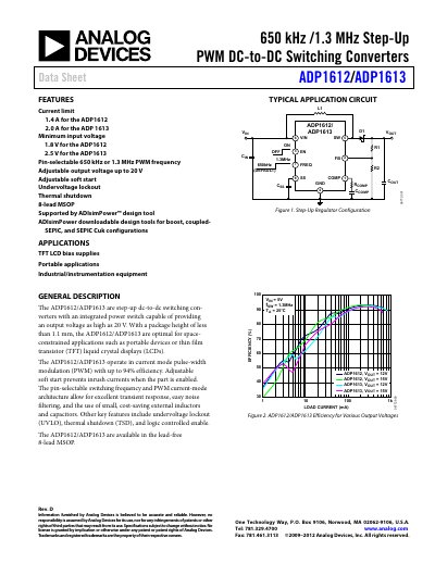
The ADP1612 and ADP1613 are step‑up DC‑to‑DC switching converters with an integrated power switch, offering adjustable output up to 20 V and high efficiency (up to 94 %). They are packaged in an 8‑lead MSOP and target space‑constrained applications such as portable devices and TFT LCD bias supplies. Features include current‑limit of 1.4 A (ADP1612) or 2.0 A (ADP1613), pin‑selectable switching frequency (650 kHz or 1.3 MHz), soft‑start, UVLO, and thermal shutdown.
The datasheet details electrical specifications, absolute maximum ratings, pin functions, typical performance curves, and design guidelines such as inductor and capacitor selection. It also includes a typical application circuit, PCB layout recommendations, outline dimensions, and an ordering guide for the MSOP package.
| Input Voltage (VIN) Range | ADP1612: 1.8 V–5.5 V; ADP1613: 2.5 V–5.5 V |
|---|---|
| Maximum Output Voltage | 20 V |
| Current Limit | ADP1612: 1.4 A; ADP1613: 2.0 A |
| Switching Frequency Options | 650 kHz or 1.3 MHz (pin‑selectable) |
| Package | 8‑lead MSOP |
The converters can be adjusted to provide up to 20 V output.
ADP1612 operates from 1.8 V to 5.5 V input.
The FREQ pin selects 650 kHz when tied to ground or 1.3 MHz when tied to VIN.