
This document introduces the Fuji IGBT-IPM Application Manual released by Fuji Electric Device Technology Co., Ltd. in September 2004. The manual provides detailed information on the characteristics of IGBT-IPM, the characteristics of each series of IPM, the meaning of model and batch numbers, product lineup, and external dimensions. It also includes explanations of terminal symbols and terminology, functional descriptions, application circuit examples, heat dissipation design, precautions for use, and troubleshooting methods when faults occur.
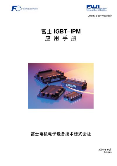
This document provides an overview of Fuji Electric IGBT‑IPM (Intelligent Power Module) families, including R‑IPM, R‑IPM3 and Econo IPM series. It explains the module’s built‑in driver, protection circuits, braking function and terminal layout.
The note also contains application circuit examples, guidelines for heatsink selection, wiring recommendations, usage precautions and detailed fault‑diagnosis procedures to help designers integrate the modules safely and reliably. This manual is written in Chinese.
| Control input terminal spacing | 2.54 mm (standard pitch) |
|---|---|
| Main terminal fastening | M5 screw, suitable for high current |
| Built‑in protection functions | Over‑current (OC), short‑circuit (SC), undervoltage (UV), over‑temperature (TcOH, TjOH), alarm output (ALM) |
The module includes over‑current (OC), short‑circuit (SC), undervoltage (UV), over‑temperature (TcOH, TjOH) and an alarm output (ALM).
The control input terminals use a standard 2.54 mm pitch.
Select a heatsink according to the method described in the thermal design section, considering the module’s power loss and operating temperature.
Model numbers indicate series, voltage rating and current rating, while batch numbers encode production month and year.