
This document describes the features and characteristics of the MAST5-1C-U17 IGBT driver board, including its built-in 1-channel IGBT driver, isolated DC-DC function, VCE detection for short circuit protection, and undervoltage protection. The board also has power and pulse indicators, and supports various input levels through a flat wire interface.
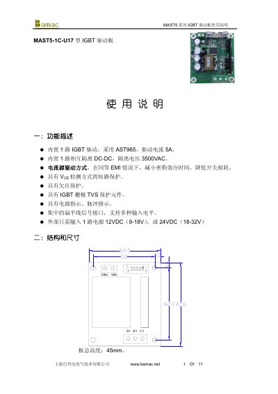
This manual describes the MAST5 series IGBT driver board (model MAST5-1C-U17) produced by Bamak. It outlines the board’s main functions, including a built‑in AST965 driver delivering 5 A drive current, 3500 VAC isolation, short‑circuit and undervoltage protection, and a flat‑cable interface supporting multiple input levels.
The document also details the electrical specifications, pin definitions, signal input requirements, power supply connections, and recommended component values for different driving modes. Safety notes cover protection‑signal handling, short‑circuit timing adjustment, and thermal considerations for reliable operation. This manual is written in Chinese.
| Driver current | 5 A |
|---|---|
| Isolation voltage | 3500 V AC |
| Maximum power consumption | 10 W |
| Operating temperature range | -25 °C to 70 °C |
| Supply voltage (24 V) | 24 ± 4 V |
| Supply voltage (12 V) | 12 ± 2 V |
| Switching frequency | 40 kHz |
The board provides an isolation voltage of 3500 VAC.
The board accepts either 12 VDC (9‑18 V) or 24 VDC (18‑32 V) power inputs.
Install a capacitor on the Cx pin; each 1000 pF adds roughly 1 µs of delay to the protection response.