
Key facts
- Manuals
- 3
- Languages
- ZH
- Last added
- 2011-11-17
Featured MAST5 manuals
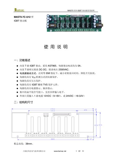
Bamac MAST5-7C-U12 IGBT Drive User Manual
This manual describes the MAST5‑7C‑U12 IGBT drive board, a 7‑channel IGBT module with integrated protection and configurable voltage levels. It outlines the functional features, dimensions, pin assignments, and signal interfaces for both 12 V and 24 V power supplies.
The document includes detailed wiring diagrams, protection signal definitions, power‑source parameters, error‑output behavior, and a full set of electrical specifications. Precautions for installation and thermal management are also provided. This manual is written in Chinese.
Covers: Functional Description · Dimensions · Pin Assignment · Signal Input and Output · Protection Signals · Power Source Parameters
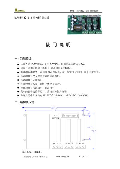
Bamac MAST5-3C-U12 IGBT Drive User Manual
The MAST5‑3C‑U12 is a three‑channel IGBT driver board that provides 5 A per channel and up to 2500 VAC isolation. It supports 12 VDC (9‑18 V) or 24 VDC (18‑32 V) external power and includes built‑in TVS protection, short‑circuit protection, and signal interfaces for multiple control signals.
The manual describes the functional overview, mechanical dimensions, pin assignments, wiring diagrams, signal levels, protection signals, and recommended operating conditions. Safety precautions and installation tips are also provided to ensure reliable operation in high‑frequency (up to 20 kHz) applications. This manual is written in Chinese.
Covers: Functional Description · Mechanical Dimensions · Wiring and Pin Assignment · Signal Interface · Protection Signals · Power Supply Requirements
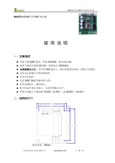
Bamak MAST5-1C-U17 IGBT Driver Board User Manual
This manual describes the MAST5 series IGBT driver board (model MAST5-1C-U17) produced by Bamak. It outlines the board’s main functions, including a built‑in AST965 driver delivering 5 A drive current, 3500 VAC isolation, short‑circuit and undervoltage protection, and a flat‑cable interface supporting multiple input levels.
The document also details the electrical specifications, pin definitions, signal input requirements, power supply connections, and recommended component values for different driving modes. Safety notes cover protection‑signal handling, short‑circuit timing adjustment, and thermal considerations for reliable operation. This manual is written in Chinese.
Covers: Function Description · Structure and Dimensions · Connections and Description · Flat Cable Pin Definitions · Signal Input Description · Protection Signal Output Description
Latest MAST5 manuals
Bamac MAST5-7C-U12 IGBT Drive User Manual
User Manual 11 pages · 231 KB · ZHThe Bamac MAST5-7C-U12 IGBT drive manual provides functional description, wiring diagrams, specifications, and safety notes for the 7‑channel IGBT board.
Bamac MAST5-3C-U12 IGBT Drive User Manual
User Manual 11 pages · 210 KB · ZHUser manual for the Bamac MAST5‑3C‑U12 IGBT drive board, covering functions, wiring, specifications and safety notes.
Bamak MAST5-1C-U17 IGBT Driver Board User Manual
User Manual 11 pages · 198 KB · ZHThe Bamak MAST5-1C-U17 IGBT driver board user manual provides functional description, connections, specifications, and safety guidelines.
Which document do I need?
User Manual
Day-to-day operation, settings and troubleshooting. Start here if the product is already set up.
Questions answered in MAST5 manuals
What input voltage ranges are supported by the MAST5‑7C‑U12 board?
The board can be powered with either 12 V or 24 V supplies, with VDD‑VSS ranges of 9‑18 V for 12 V operation and 18‑32 V for 24 V operation.
How many independent IGBT channels does the board provide?
The MAST5‑7C‑U12 board provides seven independent IGBT channels.
What is the isolation voltage of the MAST5‑3C‑U12 board?
The board provides an isolation voltage of 2500 VAC.
What external power voltage does the board require?
It can be powered from a single 12 VDC source (9‑18 V range) or a 24 VDC source (18‑32 V range).
What is the isolation voltage of the MAST5-1C-U17 driver board?
The board provides an isolation voltage of 3500 VAC.
What supply voltages can be used with the driver board?
The board accepts either 12 VDC (9‑18 V) or 24 VDC (18‑32 V) power inputs.