
Promag 50 electromagnetic flow measurement system operation manual. This manual provides detailed information on the installation, electrical connection, etc. of the product.
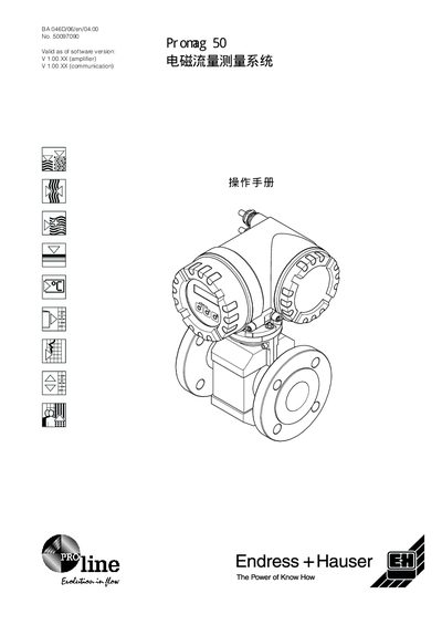
This manual explains the proper installation of the Pronag 50 flow meter, including recommended pipe orientation, avoidance of high‑point installations, and the use of vent tubes or siphon tubes for downward pipelines. It also covers vibration resistance, inlet and outlet pipe sizing, and grounding requirements to ensure reliable measurement.
Electrical connection details, signal output options, and fault handling procedures are described, with tables of terminal assignments and output signal ranges. The document includes specifications such as operating temperature, cable resistance, and capacitance for proper system integration. This manual is written in Japanese.
| Operating temperature | 20…+70 °C |
|---|---|
| Cable resistance | 3787 Ω/km |
| Capacitance per metre | 120 pF/m |
| Impedance | 508 Ω/km |
| Signal output range (standard) | 0‑20 mA |
| Signal output range (4‑20 mA) | 4‑20 mA |
| Signal output range (HART) | HART 4‑20 mA |
| Signal output range (NAMUR) | NAMUR 0‑20 mA |
Do not install the meter at the highest point of the pipe or directly downstream of a vertical pipe outlet, and avoid locations where bubbles can be trapped.
The inlet pipe diameter should be 5 × DN and the outlet pipe diameter should be 2 × DN.
The device can operate from 20 °C up to +70 °C.