
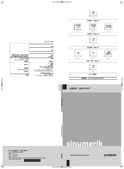
This is the SINUMERIK 802C base line technical manual, version 4.2, edition 04/2007, order number 6FC5597-4AA21-0RP1, published by Siemens AG and addressed to machine manufacturers. Its chapters follow the control system itself, the installation of the control system, installation of the display, commissioning, updating of the system software and a technical appendix.
The manual documents the connection and pin assignment of the interfaces: feed drive and spindle (X7), measuring systems (X3 to X6), the RS232 interface, the handwheel (X10), NC READY, digital inputs (X100 to X105) and digital outputs (X200 to X201), plus the CNC power supply and the LED displays and operator controls on the CNC unit. The commissioning part covers general rules, data backup, machine data (MD) and setting data (SD), PLC startup and PLC modes, PLC programming, the machine control panel layout, program and data management, downloading/uploading the PLC user program, the PLC user interface signals and the machine data and setting data tables. This manual is written in Chinese.
It is version 4.2, edition April 2007, with order number 6FC5597-4AA21-0RP1.
The appendix lists display machine data, general machine data, channel-specific machine data, axis-specific machine data and setting data.
It covers the address area, data area, CNC signals, channel signals, mode group/feed signals, MMC exchange signals, machine control panel (MCP) signals, PLC machine data and user memory.