
This is a user manual for OLED logic boards. It introduces the features and usage methods of the logic board, and provides a detailed list of components and usage instructions.
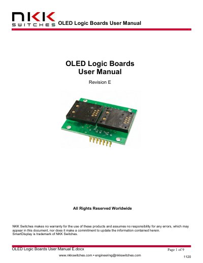
This document provides detailed instructions for using NKK Switches OLED logic boards, which are PCBs designed to mount and control OLED SmartDisplays. It covers features, part number configurations, connector pinouts, board dimensions, schematics, and key terms. The boards support daisy-chaining via 14-pin ribbon cables and include glue logic for serial conversion. Custom designs are available upon request.
The manual also includes technical specifications for connectors, pin functions, and communication formats, as well as a warranty section limiting liability to one year for manufacturing defects.
They are used for mounting OLED 64x48 SmartDisplays or 52x36 SmartDisplays into panels and system assemblies.
Many logic boards can be daisy-chained via 14-pin ribbon cables.
The boards require a 3.3V supply connected to pin 7 and a 16V supply connected to pin 8.