
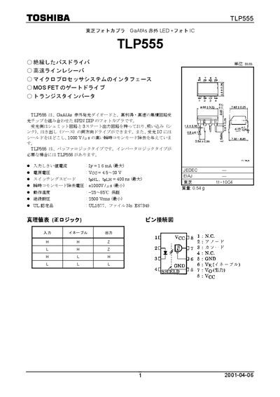
The TLP555 is an 8‑pin DIP optocoupler that combines a GaAs infrared LED with a high‑gain, high‑speed phototransistor. It provides both sink and source drive capability and includes a Schmitt‑trigger output stage. The device is intended for isolation in bus drivers, microprocessor interfaces, MOS‑FET gate drives and transistor inverters.
Key specifications include a typical switching time of 400 ns, isolation voltage of 2500 Vrms, operating temperature range –40 °C to 85 °C, and a supply voltage range of 4.5 V to 20 V. Recommended input high‑level current is 2 – 5 mA, and the device is UL‑1577 certified. This manual is written in Japanese.
| Isolation Voltage | 2500 Vrms (minimum) |
|---|---|
| Supply Voltage (VCC) | 4.5 V – 20 V |
| Switching Speed (tpHL / tpLH) | 400 ns (maximum) |
| Operating Temperature Range | -40 °C – 85 °C |
The TLP555 provides a minimum isolation voltage of 2500 Vrms.
The typical switching time (tpHL/tpLH) is specified as up to 400 ns.
The recommended input high‑level current is between 2 mA and 5 mA.