
This document is the instruction manual for Anderson Instrument AGW Life Sciences Series Guided Wave Radar
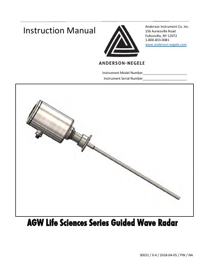
This manual provides installation, programming, and troubleshooting instructions for the AGW Life Sciences Series Guided Wave Radar. It covers mechanical installation, wiring, power-on procedures, and programming using either the A-N E-Scope software or the display unit. The device uses TDR (Time Domain Reflectometry) to measure liquid levels in tanks up to 10 ft (3 m) high, suitable for foaming media and water-based solutions with a minimum dielectric constant of 2.
Technical specifications include a rod length of up to 120 inches, process pressure up to 230 psi, and output signals of 4-20 mA and HART. The manual also details maintenance, calibration, and troubleshooting steps for common issues such as incorrect level readings or communication errors.
| Rod Length | 120 in max. |
|---|---|
| Process Pressure | 230 psi (16 bar) max. |
| Output Signal | 4...20 mA, galvanically separated from housing, 2-wire loop |
| Accuracy | +/-0.2” (3.8mm) |
| Repeatability | +/- .08” (2mm) |
| Temperature Range | 14...284 °F (-10...140 °C) |
| Weight | 920 g with rod length of 1.5 m |
The AGW uses TDR (Time Domain Reflectometry) to send pulses along a conductive rod. When a pulse reflects off the medium surface, it is detected and converted into a level measurement proportional to the time of flight.
The device is powered by 18–36 V DC and provides 4–20 mA and HART output signals, galvanically isolated from the housing.
Check for obstructions in the tank, ensure the probe is clean, and adjust the detection delay or threshold level. Use the E-Scope oscilloscope function to analyze the signal.