
This document is an installation and operating manual for Anderson-Negele Weighing System Load Stand® II, which introduces the product's features and characteristics, such as product description, installation method, and operating method.
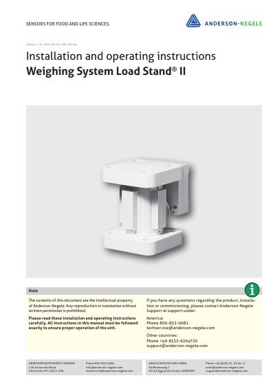
The Load Stand® II is a direct vessel-to-foundation structural member designed for continuous inventory monitoring and control. It features a monolithic design suitable for vessels with loads of 45,000 kg (100,000 lbs) or more, utilizing field-proven Kistler-Morse sensors. The system allows for maintenance-free weight measurements with solid-state strain sensors that are field replaceable.
| Maximum Current | 15.52 mA @ 12 VDC excitation |
|---|---|
| Humidity Protection | Non-condensing |
| Materials (Pedestal) | Carbon Steel 1.0044 (ASTM A53 GR) |
| Materials (Flanges) | Carbon Steel 1.0459 (ASTM A36) |
| No Load Output | ±50 mV |
| Temperature Range (Standard) | -18...38 °C (0...100 °F) |
It is a direct vessel-to-foundation structural member designed for dependable and accurate continuous inventory monitoring and control.
The system is available for loads of up to 453,000 kg (1,000,000 lbs) per support point.
The maximum current is 15.52 mA when using 12 VDC excitation.
You must leave a 6 mm (1/4") gap between the nut and washer to allow for positioning.