
This manual introduces the features and characteristics of Motortronics TE-RTD12 Relay Device.
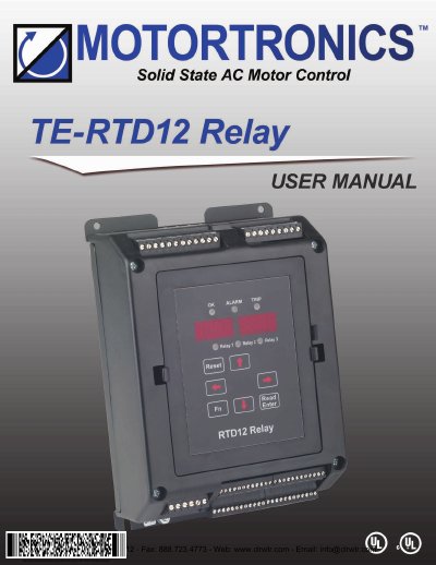
The Motortronics TE-RTD12 Relay Device is an advanced monitoring unit designed for motor systems. It features 12 built-in RTD inputs for temperature monitoring, 3 programmable output relays, and isolated analog inputs and outputs. The device supports differential current feedback monitoring and includes an RS485 communication port for integration with PLCs or SCADA systems.
| RTD Inputs | 12 built-in RTD inputs |
|---|---|
| Output Relays | 3 programmable output relays (5A) |
| Analog Inputs | 2 isolated analog inputs (4-20mA) |
| Analog Output | 1 isolated analog output (4-20mA) |
| Digital Inputs | 3 isolated digital inputs |
| Communication Port | RS485 (2 wire) |
| Power Supply | 110 - 240 Vac 1Ø 50 / 60 Hz |
| Dimensions | 225mm x 157.2mm x 77.7mm (H x W x D) |
Use a fuse protection of 2A 240VAC 5kA RK5 or equivalent fuse.
Yes, the device can be mounted on a back panel using the mounting bracket or DIN-Rail mount.
The default name for RTD #1 is Stator #1, and for RTD #2 is Stator #2.