
The document is about the installation and maintenance instructions for RTS151KEY remote test station. This product is an automatic fire detector accessory for testing remote duct and beam detectors.
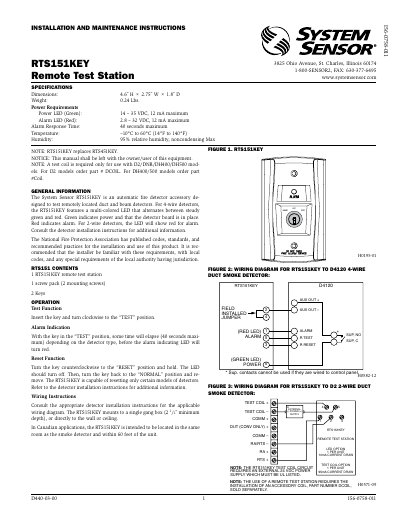
The RTS151KEY is an automatic fire detector accessory designed to test remotely located duct and beam detectors. It features a multi-colored LED that indicates power (green) or alarm (red) status. The unit requires a test coil for certain detector models and can be mounted in a single gang box or directly to walls or ceilings. It operates on 14–35 VDC for power and 2.8–32 VDC for alarm, with a maximum alarm response time of 40 seconds. Wiring diagrams are provided for compatibility with various detector models including D2, DNR, DH400, DH500, and BEAM1224 series.
| Dimensions | 4.6˝ H × 2.75˝ W × 1.8˝ D |
|---|---|
| Weight | 0.24 Lbs. |
| Power Requirements (Power LED) | 14 – 35 VDC, 12 mA maximum |
| Power Requirements (Alarm LED) | 2.8 – 32 VDC, 12 mA maximum |
| Alarm Response Time | 40 seconds maximum |
| Temperature Range | –10°C to 60°C (14°F to 140°F) |
| Humidity | 95% relative humidity, noncondensing |
Green indicates power and that the detector board is in place.
Red indicates alarm.
A test coil is required; order part # DCOIL for D2 models or part # Coil for DH400/500 models.
Turn the key counterclockwise to the “RESET” position and hold. The LED should turn off. Then, turn the key back to the “NORMAL” position and remove.