
Key facts
- Manuals
- 4
- Models
- 1
- Languages
- EN
- Last added
- 2023-10-26
System Sensor models by category
Featured System Sensor manuals
System Sensor M2 Digital Audio DVC Digital Voice Command Installation, Programming and Operations Manual
This document serves as the Installation, Programming, and Operations Manual for the System Sensor M2 Digital Audio DVC Digital Voice Command system. It is designed for use within Fire Alarm & Emergency Communication Systems, detailing the limitations and proper usage of such life safety systems. The text emphasizes that while these systems provide early warning, they do not guarantee protection against property damage or loss of life and should not replace insurance.
The manual outlines critical limitations regarding smoke and heat detectors, audible warning devices, and power requirements. It stresses the importance of proper installation locations, adherence to NFPA 72 standards, and regular maintenance by authorized professionals to ensure the system functions correctly during a fire or life safety event.
Covers: System Limitations · Smoke Detector Limitations · Heat Detector Limitations · Audible Warning Devices · Power Requirements · Maintenance Requirements
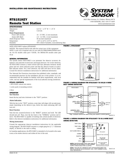
System Sensor RTS151KEY Remote Test Station Installation and Maintenance Instructions
The RTS151KEY is an automatic fire detector accessory designed to test remotely located duct and beam detectors. It features a multi-colored LED that indicates power (green) or alarm (red) status. The unit requires a test coil for certain detector models and can be mounted in a single gang box or directly to walls or ceilings. It operates on 14–35 VDC for power and 2.8–32 VDC for alarm, with a maximum alarm response time of 40 seconds. Wiring diagrams are provided for compatibility with various detector models including D2, DNR, DH400, DH500, and BEAM1224 series.
Covers: General Information · Operation · Wiring Instructions · Specifications · Wiring Diagrams
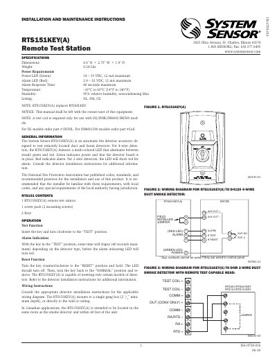
System Sensor RTS151KEY(A) Remote Test Station Installation and Maintenance Instructions
The RTS151KEY(A) is an automatic fire detector accessory designed to test remotely located duct and beam detectors. It features a multi-colored LED that indicates power (green) or alarm (red) status. The device is intended for use with specific detector models and requires a test coil for certain models. Installation involves mounting to a single gang box or directly to wall/ceiling, with wiring diagrams provided for various detector types. The device can reset certain detector models, and its operation is controlled via a key switch with TEST, RESET, and NORMAL positions. A three-year limited warranty is provided for defects in materials and workmanship under normal use.
Covers: General Information · Operation · Wiring Instructions · Wiring Diagrams · Three-Year Limited Warranty
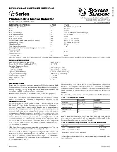
System Sensor 2W-B, 2WT-B, 4W-B, 4WT-B Photoelectric Smoke Detectors Installation and Maintenance Instructions
This document provides installation and maintenance instructions for System Sensor’s 2-wire and 4-wire photoelectric smoke detectors. It includes details on detector features, wiring, mounting, and LED status indicators. The detectors are designed for open area protection and must be used with compatible UL-listed control panels. Regular maintenance and cleaning are required to ensure proper function, with annual cleaning recommended.
The detectors feature advanced optical sensing chambers and microprocessors that automatically reset sensitivity after contamination. Models 2WT-B and 4WT-B include built-in thermal sensors and freeze detection. Installation is simplified with pre-wired mounting bases compatible with drywall fasteners. LED indicators show status: green for normal, red for maintenance or alarm, and blinking patterns during power-up.
Covers: Installation · Maintenance · Wiring Diagrams · LED Status Indicators · Mounting · Thermal and Freeze Detection
Latest System Sensor manuals
System Sensor M2 Digital Audio DVC Digital Voice Command Installation, Programming and Operations Manual
User Manual 120 pages · 3.4 MB · ENThis manual covers the installation, programming, and operation of the System Sensor M2 Digital Audio DVC Digital Voice Command system for fire alarm and…
System Sensor RTS151KEY Remote Test Station Installation and Maintenance Instructions
User Manual 2 pages · 652 KB · ENInstallation and maintenance guide for System Sensor's RTS151KEY remote test station for duct and beam smoke detectors.
System Sensor RTS151KEY(A) Remote Test Station Installation and Maintenance Instructions
Installation Guide 2 pages · 935 KB · ENInstallation and maintenance guide for System Sensor's RTS151KEY(A) remote test station for duct and beam smoke detectors.
System Sensor 2W-B, 2WT-B, 4W-B, 4WT-B Photoelectric Smoke Detectors Installation and Maintenance Instructions
Installation Guide 4 pages · 323 KB · ENInstallation and maintenance guide for System Sensor photoelectric smoke detectors models 2W-B, 2WT-B, 4W-B, and 4WT-B.
Which document do I need?
User Manual
Day-to-day operation, settings and troubleshooting. Start here if the product is already set up.
Installation Guide
Mounting, wiring and first power-up. Read it before the hardware goes in.
Questions answered in System Sensor manuals
What is the purpose of the DVC Digital Voice Command system?
It is part of an emergency communication system that can broadcast a mass notification message.
What standard must smoke detector installation follow?
The current edition of the National Fire Protection Association Standard 72 (NFPA 72).
What does the green LED indicate?
Green indicates power and that the detector board is in place.
From: System Sensor RTS151KEY Remote Test Station Installation and Maintenance Instructions
What does the red LED indicate?
Red indicates alarm.
From: System Sensor RTS151KEY Remote Test Station Installation and Maintenance Instructions
What does the green LED indicate?
Green indicates power and that the detector board is in place.
From: System Sensor RTS151KEY(A) Remote Test Station Installation and Maintenance Instructions
What does the red LED indicate?
Red indicates alarm.
From: System Sensor RTS151KEY(A) Remote Test Station Installation and Maintenance Instructions