
This is the instruction manual of DODGE® PARA-FLEX® Couplings
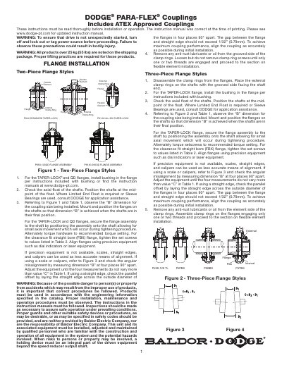
This guide provides step-by-step instructions for installing DODGE PARA-FLEX® couplings, including two-piece and three-piece flange styles. It details alignment procedures using precision tools or alternative methods, torque specifications for clamp ring screws, and flexible element installation. Safety warnings are included to ensure proper handling and operation.
The document also references ATEX-approved couplings and includes tables for mounting dimensions and set screw torque values by coupling size. Guards must be installed to contain the coupling in case of failure.
| Maximum Angular Misalignment | Value "C" in Table 1 |
|---|
Use precision equipment like dial indicators or laser equipment; if unavailable, use scales, straight edges, and calipers with specified tolerances.
The gap between the flange and straight edge should not exceed 1/32" (0.79mm).
Clean the area with a solvent such as Xylene (Xylol) to remove grease, oil, wax, and dirt.
Tighten each clamp ring screw in succession to the torque specified in Table 1 using a torque wrench.