
This is an instruction manual for DODGE PARA-FLEX® High Speed and Flywheel Couplings
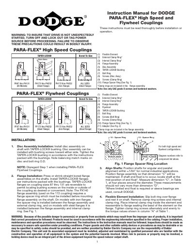
This manual provides installation and operation instructions for Dodge PARA-FLEX High Speed and Flywheel Couplings. It details the procedures for installing disc assemblies and flange assemblies on shafts, including specific steps for TAPER-LOCK bushings and flange spacers. The guide emphasizes safety precautions, such as locking out power sources before installation, and specifies the use of SAE grade 8 screws and hardened washers.
| Shaft Alignment Tolerance | ±1/64" |
|---|---|
| Screw Grade | SAE grade 8 |
| Coupling Sizes | PH/PF 87 through 252 |
Turn off and lock out or tag the power source to ensure the drive is not unexpectedly started.
Only SAE grade 8 screws and hardened washers should be used.
Slip the bolt ring over the flange, remove the clamp ring screws and internal clamp ring, place the internal clamp ring inside the element, and reassemble to the flange.