
NTC-6000 Quick Start Guide, Select Your Output, Adjust DIP Switches, DIP Switch Settings, After DIP switch selections are made, re-assemble the NTC-6000 cover, Make Your Connections, Calibrate The NTC-6000 to the LVDT
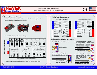
This document provides instructions for the NewTek NTC-6000 sensor controller, specifically focusing on selecting output parameters via DIP switches. Users are guided on how to adjust settings for frequency, filter, RS-485 bus address, output range, and primary drive before reassembling the unit.
| Power Supply | 11-30VDC |
|---|---|
| Frequency Options | 2.5, 5, 7.5, 10 KHz |
| Filter Options | 100, 110 Hz |
| RS-485 Bus Address | 0-1 |
| Primary Drive | LOW, HIGH |
| Output Invert | NORM, INV |
| Error Detection | DISA, NORM |
| Origin | Pennsauken, NJ USA |
Remove the exterior cover by depressing the tabs on top and bottom and removing the cover.
Press and hold both buttons for 3 seconds until the red PWR LED blinks, then move the core to the NULL position to illuminate the Green N light.
The unit requires a power supply between 11-30VDC.