
TL1464I is a high-speed drive controller for PNP power transistors. It features an internal 1.5V regulator, a low start-up voltage of 3.1V, internal short-circuit protection, internal undervoltage lockout protection, internal shut-down circuit by channel, and controllable base current of external transistor.
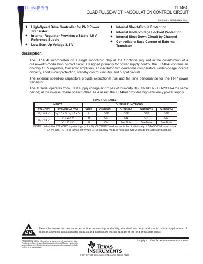
The TL1464I is a quad pulse-width-modulation control circuit designed primarily for power supply control. It incorporates all necessary functions on a single monolithic chip, including an on-chip 1.5 V regulator, four error amplifiers, an oscillator, dead-time comparators, undervoltage lockout circuitry, and short-circuit protection. The device operates from a low start-up voltage of 3.1 V and provides high-efficiency power supply performance.
| Operating free-air temperature | -20°C to 75°C |
|---|
The TL1464I operates from a low start-up voltage of 3.1 V.
Yes, the device includes internal short-circuit protection circuitry.