
Texas Instruments TL1451A Dual Pulse-Width-Modulation Control Circuits Datasheet

This document is the datasheet of TL1451A. It provides detailed information about the features and characteristics of TL1451A, including internal structure, working principle and application scenarios.
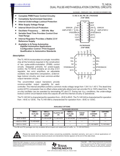

Texas Instruments TL1451A Dual Pulse-Width-Modulation Control Circuits Datasheet - cover page
Brand
Texas Instruments
Category
Other Electronics
Document type
Datasheet
Language
English
Pages
29
File format
PDF
File size
425 KB
Published
09 August, 2012
Updated
30 September, 2023
Model
TL1451A
MD5 checksum
9B89319C11061E1C49B4E327F48029E7

About this manual

The TL1451A is a monolithic integrated circuit designed primarily for power-supply control. It incorporates all functions required for constructing two pulse-width-modulation (PWM) control circuits on a single chip. Key features include an on-chip 2.5-V reference regulator, two error amplifiers, an adjustable oscillator, and dual common-emitter output transistor circuits.

What's inside

  • Functional Block Diagram
  • Absolute Maximum Ratings
  • Recommended Operating Conditions
  • Electrical Characteristics
  • Reference Section
  • Undervoltage Lockout Section
  • Short-Circuit Protection Control
  • Oscillator Section
  • Dead-Time Control Section
  • Error-Amplifier Section

Specifications

Oscillator frequency500 kHz Max
Collector output current20 mA
Operating temperature (Q suffix)-40°C to 125°C
Operating temperature (M suffix)-55°C to 125°C

Frequently asked questions

What is the maximum oscillator frequency?

The maximum oscillator frequency is 500 kHz.

Does the device include internal protection?

Yes, it includes internal undervoltage lockout and short-circuit protection.

Download PDF (425 KB)

More Texas Instruments Manuals


View all Texas Instruments manuals →