
This is an application note about L6563H 250 W TM PFC demonstration board, which introduces the main features and circuit description of the product.
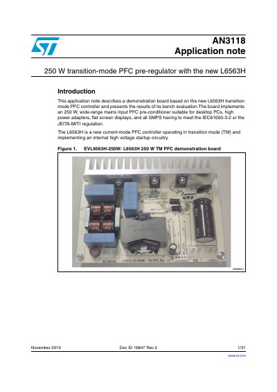
The document details an evaluation board based on the new L6563H current-mode PFC controller operating in transition mode. The design implements a 250 W, wide-range mains input pre-conditioner suitable for desktop PCs and high-power adapters, ensuring compliance with EN61000-3-2 or JEITA-MITI regulations.
The application note covers the main characteristics of the SMPS, including electrical diagrams, bill of materials, test results with significant waveforms (such as harmonic content and efficiency), layout hints, thermal maps, and EMI filtering measurements. It also explains the circuit description, startup operation, power management functions, and interfacing capabilities.
| Rated output power | 250 W |
|---|---|
| Regulated output voltage | 400 V |
| Line voltage range | 90 to 265 Vac |
| Minimum switching frequency | 46 kHz |
| Maximum ambient temperature | 50 °C |
The minimum estimated efficiency is 93% at an input voltage of 90 Vac and output power of 250 W.
The demonstration board provides a continuous rated output power of 250 W.
This design delivers a regulated output voltage of 400 V to the cascaded converter.
The IC automatically restarts once the RUN pin voltage rises above 0.88 V.