
This application note describes how to connect the STA350BW 2.0-channel demonstration board, evaluate its performance, and avoid critical issues in the PCB schematic and layout.
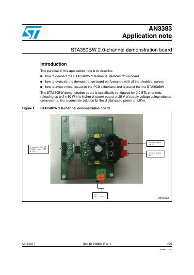
The document provides instructions on how to connect the STA350BW 2.0-channel demonstration board and evaluate its performance using electrical curves such as efficiency, frequency response, crosstalk, SNR, THD, and FFT. It details the specific configuration for 2.0 BTL channels capable of delivering up to 2 x 50 W into a 6 ohm load at 25 V supply voltage.
| Channels | 2.0-channel |
|---|---|
| Configuration | 2 BTL channels |
| Max Power Output (6 ohm) | 2 x 50 W |
| Supply Voltage Range | 4.5 V to 26 V |
The test setup includes Audio Precision System 2700, a DC power supply (4.5V to 26V), a Digital oscilloscope TDS3034B by Tektronix, and a PC with APWorkbench GUI.
Connect the positive voltage of the 24V DC power supply to the +Vcc pin and negative to GND. Connect the APWorkbench board to the J1 connector.