
This document is the user guide of SSM2804 audio subsystem evaluation board. It introduces the features of this evaluation board, including differential or single-ended inputs, PCB footprint for optional EMI filter, USB hardware interface and Windows-based evaluation software.
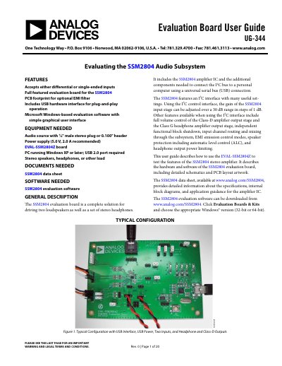
The SSM2804 evaluation board is a complete solution for driving two loudspeakers and stereo headphones. It includes the SSM2804 amplifier IC and components to connect the I2C bus to a PC via USB. The board features a graphical user interface for controlling gain, volume, EMI modes, and protection settings.
The guide details the hardware configuration, including power supply connections (PVDD and AVDD), input/output signal headers, and jumper settings for shutdown and I2C sources. It also covers the software setup and functional blocks for controlling the amplifier's Class-D and Class-G stages.
| Input Type | Differential or single-ended |
|---|---|
| Power Supply PVDD | 2.7 V to 5.5 V |
| Power Supply AVDD | 2.5 V to 3.6 V |
| Gain Adjustment Range | 30 dB in 1 dB steps |
| USB Current Limit | 500 mA |
The board requires two external DC power supplies: PVDD (2.7 V to 5.5 V) and AVDD (2.5 V to 3.6 V), or a 5 V USB power supply.
A 2-pin jumper (JP10) controls the amplifier; inserting it activates the amplifier, while removing it shuts down both channels.
The LEDs indicate status such as 5 V power supply (Red), I2C mode (Yellow), GPIO debug (Blue), and USB power switch enabled (Blue).