
This document is the user guide for the AD9642/AD9634/AD6672 analog-to-digital converters evaluation board. It describes the features and characteristics of the evaluation board, as well as the required equipment and software.
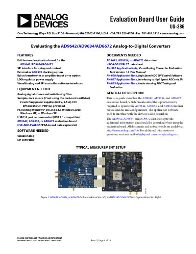
The document is a User Guide (UG-386) for the AD9642/AD9634/AD6672 evaluation board. It details the support circuitry required to operate these high-speed Analog-to-Digital Converters in various modes and configurations, including power supply options, input signal requirements, and clocking setups.
The guide covers default operation settings, jumper selection for configuring analog inputs (balun or amplifier), and clock circuits (transformer-coupled or AD9523). It also describes the necessary equipment, software interfaces like VisualAnalog and SPI controller, and provides quick start procedures for testing.
| Operating Voltage (Wall Outlet) | 100 V ac to 240 V ac at 47 Hz to 63 Hz |
|---|---|
| Power Supply Output | 6 V, 2.5 A maximum |
| Analog Input Impedance | 50 Ω |
| Nominal Input Drive Level | 10 dBm (2 V p-p full scale) |
| Clock Input Impedance | 50 Ω terminated |
The board includes VisualAnalog and SPI controller software interfaces for setup and control.
Yes, the board is set by default to use an external clock generator connected to J506.
The source must have very low phase noise (<1 ps rms jitter) and require proper filtering of harmonics.