
The RP904 series are CMOS-based PWM/PFM step-down DC/DC converters with synchronous rectifier, low supply current and through mode. The DC/DC converter of the RP904X consists of an oscillator, a PWM/PFM control circuit, a reference voltage unit, an error amplifier, a soft-start circuit, protection circuits, a protection against miss operation under low voltage (UVLO), PWM-DC to DC converter or bypass switch alternative circuit, a chip enable circuit, and a driver transistor. A high efficiency step-down DC/DC converter can be easily composed of this IC with only a few kinds of external components, or an inductor and capacitors. The output voltage of the DC/DC converter has two kinds of output voltage, and alternative with the VSEL pin. The RP904 series are PWM/PFM step-down DC/DC converter, thus, when the load current is small, the operation can be switching into the PFM operation from PWM control if the user chooses the VFM mode. As protection circuits, the current limit circuit which limits peak current of Lx at each clock cycle, and the latch type protection circuit which works if the term of the over-current condition keeps on a certain time in PWM mode. Latch-type protection circuit works to latch an internal driver with keeping it disable. To release the protection, after disable this IC with a chip enable circuit, enable it again, or restart this IC with p-MOSFET.
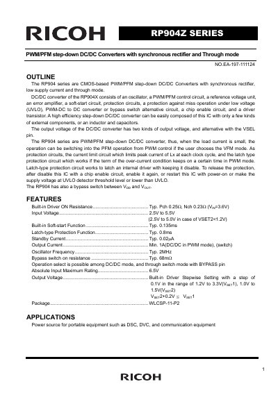
The RP904 series are CMOS-based PWM/PFM step-down DC/DC converters featuring synchronous rectification, low supply current, and a through mode. The RP904Z model includes an oscillator, PWM/PFM control circuit, error amplifier, and various protection circuits such as UVLO and latch-type over-current protection. It supports output voltage selection via the VSEL pin and allows operation switching between PWM and PFM modes based on load current and user configuration.
| Input Voltage | 2.5V to 5.5V |
|---|---|
| Output Current (PWM mode) | Min. 1A |
| Oscillator Frequency | Typ. 2MHz |
| Standby Current | Typ. 0.02uA |
| Operating Temperature Range | -40 to +85 °C |
| Output Voltage Range (Vset1) | 1.2V to 3.3V |
| Output Voltage Range (Vset2) | 1.0V to 1.5V |
The typical oscillator frequency is 2MHz.
Yes, the operation can switch into PFM mode from PWM control if the user chooses the VFM mode.
The minimum output voltage for Vset1 is 1.2V.