
The R5524N series USB high side switch IC is a CMOS-based USB high side switch IC. The R5524N is a protection IC used in the power line of USB with built-in current limit circuit, thermal shutdown circuit, and under-voltage lockout circuit (UVLO). The R5524N001 has the built-in latch-off type over-current limit circuit. When the over-current is detected, the protection circuit becomes active and the switch-transistor is turned OFF. The R5524N002 has the built-in over current protection circuit as the constant current type. It detects as the over-current condition, if the current flows as the ITH defined. Then operating the switch transistor to limit the output current to be the constant current defined by the ILIM. The SOT-23-5 package is available, which is smaller than SOT-89-5 (R5520H).
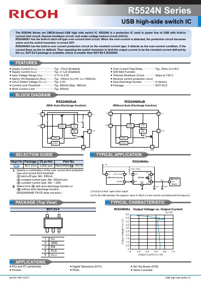
The R5524N series consists of CMOS-based high-side MOSFET switch ICs designed for Universal Serial Bus (USB) applications. These devices utilize an N-channel FET as a switching transistor, offering low on-resistance and reverse current protection. The series includes built-in protection circuits such as over-current limiting, thermal shutdown, and under-voltage lockout (UVLO).
The typical switch-on resistance is 100 mΩ when the input voltage is 5V and the output current is 500 mA.
The recommended pull-up resistance value range for the flag pin is from 10 kΩ to 100 kΩ.
For the USB standard, a capacitor value of 120 µF or more must be connected with the output pin.