
This application note introduces the use of the VTO and rT on-state characteristic model and a more accurate alternative.
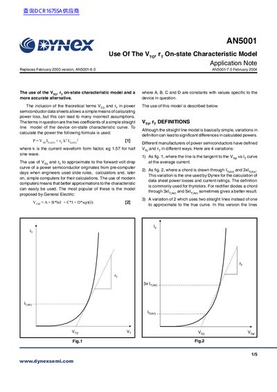
The document discusses how traditional straight-line models using coefficients Vt (threshold voltage) and r (dynamic resistance) can lead to incorrect assumptions when calculating power loss in power semiconductor devices. It highlights that while these terms originated from pre-computer calculation methods, modern computing allows for better approximations of the device's forward volt drop curve.
Using this model can lead to many incorrect assumptions because it only gives correct values at one or two points on the curve, resulting in optimistic or pessimistic answers depending on where the point is taken.
Dynex Semiconductor has determined these values for various device types, which are listed in Table 2 (for thyristors) and Table 3 (for diodes).